
Should They Be Revisited?
Nicholas S. Grundish, PhD, and Mojdeh Nikpour, PhD
Energy Exploration Technologies Inc.
Q2 2026
I. Introduction
Open the certificate of analysis for any battery-grade lithium carbonate or lithium hydroxide shipment, and you will find a familiar set of numbers. A total purity of 99.5% or higher, sodium below 200 parts per million, iron below 10, calcium below 50, sulfate below 500, and so on. These figures appear on datasheets from Albemarle and SQM, from Ganfeng and Tianqi, from brine operations in the Atacama and hard-rock converters in Western Australia. They are ubiquitous and have taken on an air of physical law. Almost as if the numbers were derived from first principles and are backed by thorough experimentation beyond reproach.
However, if you dig into the literature, there are little to no studies that give credence to these universally accepted specifications. The specifications that define “battery grade” lithium precursors are the product of a specific historical moment. They emerged from the intersection of early Japanese cell manufacturer experience in the late 1980s and 1990s, the analytical detection capabilities available at the time, the practical constraints of the dominant lithium refining routes, and an industry culture that treats material qualification as a quasi-permanent commitment. Some of the thresholds embedded in these specs are electrochemically rigorous and derived from well-understood degradation mechanisms that remain relevant today. Others are legacy artifacts, numbers that were once “below the detection limit” of available instruments or “as good as the refinery could achieve”, which hardened into requirements through repetition and qualification inertia.
As the lithium-ion battery industry evolves toward higher nickel content cathode chemistries, longer cycle life requirements, and entirely new anode and electrolyte architectures, the gap between what the specifications capture and what electrochemistry demands is widening. Some impurity thresholds that were adequate for early LiCoO₂ cells are insufficient for nickel-rich formulations that are pushed to thousands of charge-discharge cycles. Conversely, some thresholds that were set conservatively decades ago impose unnecessary cost on the supply chain without delivering meaningful benefit.
This paper traces the origin of battery-grade lithium precursor specifications, specifically for lithium carbonate and lithium hydroxide monohydrate, the two dominant cathode precursor inputs. It examines which specifications rest on solid electrochemical foundations, which were shaped by historical circumstances, and where the framework may need to evolve as cell chemistries continue to advance. The central argument is not that existing specs are wrong, but that the industry would benefit from understanding why they are what they are, so it can make informed decisions about what they should become.
II. A Brief History of Lithium as a Battery Material
From Laboratory to Commercial Cell
The foundational electrochemistry of lithium intercalation was established across three decades. In the 1970s, Stanley Whittingham at Exxon demonstrated that lithium ions could be reversibly intercalated into layered TiS₂, establishing the basic principle of the rechargeable lithium cell. In 1980, John Goodenough and his collaborators at the University of Oxford identified layered LiCoO₂ as a cathode material with a significantly higher voltage and energy density than titanium disulfide.In 1985, Akira Yoshino at Asahi Kasei showed that a carbonaceous anode could replace metallic lithium, resolving the dendrite safety problems that had plagued earlier cell designs. These three contributions (the intercalation concept, the high-voltage cathode, and the carbon anode) collectively defined the architecture that Sony commercialized for consumer electronics in 1991 as the first lithium-ion battery.
Sony’s commercialization was a watershed for the lithium supply chain. Prior to 1991, lithium carbonate was predominantly an industrial chemical consumed by the glass, ceramics, and aluminum smelting industries. Purity requirements for those applications were modest. Technical-grade lithium carbonate at 99.0% purity was adequate for glass fluxing. Even pharmaceutical-grade lithium carbonate, used in the treatment of bipolar disorder, did not require the kind of trace metal control that battery applications would demand. The jump from industrial to battery-grade lithium carbonate required not just higher total purity but a fundamentally different philosophy of impurity control. A philosophy focused on specific elements at parts-per-million and even parts-per-billion levels rather than on bulk composition.
The Early Supply Base
When Sony and its Japanese competitors Sanyo, Matsushita (now Panasonic), and later Samsung SDI and LG Chem began scaling lithium-ion cell production in the 1990s, the global lithium supply base was small and concentrated. Three companies dominated: SQM and what was then Sociedad Chilena del Litio (later acquired by Albemarle) in Chile’s Atacama salt flat, and FMC Lithium (later Livent, then Arcadium Lithium, and now a part of Rio Tinto) in Argentina. Hard-rock spodumene production in Western Australia and Chinese lepidolite processing were comparatively minor contributors at the time.
This supply base geography had direct implications for specifications. Brine-derived lithium carbonate carries a characteristic impurity fingerprint of relatively low iron and copper (because these elements are not abundant in salar brines), but elevated sodium, potassium, magnesium, boron, and sulfate from the evaporative concentration process. The early battery-grade specs were, in part, written around what these brine producers could reliably achieve after purification. This is not to say the specs were arbitrary as cell manufacturers were testing materials and observing failure modes, but the boundary between “what is electrochemically necessary” and “what the best available material happens to look like” was not always sharply drawn.
Japanese Standards and the Qualification Culture
Japanese industrial standards played a formative role. Reagent-grade chemical-purity standards provided an early reference framework, though they were not designed specifically for battery applications. More consequential were the internal specifications developed by Sony, Sanyo, and Matsushita for their own cathode precursor sourcing. These internal specs were proprietary, but their general contours became known through the supply chain and influenced subsequent standards development.
The Japanese cell manufacturing culture introduced a practice that profoundly shaped how specs would evolve or, more precisely, how they would resist evolving. Cell manufacturers qualified specific materials from specific suppliers against specific internal specifications. Once a material was qualified, any change to the specification (even a tightening of an impurity limit) required requalification. This process typically involved six to eighteen months of testing across cell builds, cycling, and safety evaluation, at significant cost. The result was a powerful incentive to leave specifications unchanged once they were established, a phenomenon that can be accurately described as qualification inertia.
III. “Battery Grade” Specifications
Before examining the electrochemical and historical basis for specific thresholds, it is useful to lay out what a typical battery-grade specification contains. The table below presents representative specifications for battery-grade lithium carbonate and lithium hydroxide monohydrate. These are composites drawn from multiple supplier datasheets and relevant standards. Individual suppliers and cell manufacturers may specify tighter or looser limits for particular parameters.
Table 1. Representative “Battery Grade” specifications for lithium carbonate and lithium hydroxide monohydrate.*
| Parameter | Li₂CO₃ (Battery Grade) | LiOH·H₂O (Battery Grade) |
|---|---|---|
| Total Purity | ≥ 99.5% Li₂CO₃ | ≥ 56.5% LiOH content |
| Na | ≤ 250–600 ppm | ≤ 20–200 ppm |
| K | ≤ 20–50 ppm | ≤ 10–30 ppm |
| Ca | ≤ 50–400 ppm | ≤ 10–200 ppm |
| Mg | ≤ 30–100 ppm | ≤ 10–30 ppm |
| Fe | ≤ 5–15 ppm | ≤ 3–10 ppm |
| Cu | ≤ 3–5 ppm | ≤ 2–5 ppm |
| Mn | ≤ 5–10 ppm | ≤ 3–5 ppm |
| Zn | ≤ 5–10 ppm | ≤ 3–5 ppm |
| Pb | ≤ 2–5 ppm | ≤ 2–5 ppm |
| Al | ≤ 10–30 ppm | ≤ 5–20 ppm |
| Si | ≤ 30–80 ppm | ≤ 20–50 ppm |
| Ni | ≤ 5–10 ppm | ≤ 5–10 ppm |
| Cr | ≤ 1–5 ppm | ≤ 1–5 ppm |
| B | ≤ 10–30 ppm | Not commonly specified |
| SO₄²⁻ | ≤ 300–1,000 ppm | ≤ 100–300 ppm |
| Cl⁻ | ≤ 30–200 ppm | ≤ 30–100 ppm |
| Loss on Ignition (LOI) or CO₂ / Residual Carbonate | ≤ 0.3–0.5% (as LOI) | ≤ 0.20–0.35% CO₂ |
| Magnetic Impurities | < 50–200 ppb (metallic Fe) | < 50–200 ppb (metallic Fe) |
| D50 Particle Size | 3–8 µm (typical) | 400–700 µm |
| Moisture | ≤ 0.3–0.5% | ≤ 0.1–0.3% (free water) |
*The ranges above represent the full spread observed across formal standards (YS/T 582-2013, GB/T 8766-2013, GB/T 11075), published producer specifications, and a review of over twenty LiOH·H₂O and over a dozen Li₂CO₃ commercial specification sheets spanning major producers, distributors, and regional suppliers across multiple continents. Premium cathode-grade material, particularly lithium hydroxide destined for high-nickel applications, is routinely delivered at the tighter end of these ranges or below. For example, premium LiOH suppliers commonly deliver Na at 20 ppm or less, while the formal GB/T 8766 T2 standard allows up to 80 ppm. The tightest commercial Ca specification observed in the LiOH dataset was 10 ppm, fifteen times below what the formal standard permits.
Several features of this table warrant comment. First, the ranges shown for each parameter reflect variation across the industry as there is no single universal “battery grade” standard, and different cell manufacturers impose different requirements depending on their cathode chemistry, cell design, and risk tolerance. Second, lithium hydroxide specifications tend to be tighter than lithium carbonate specifications for most impurities owing to production chemistry. Lithium hydroxide is recovered by crystallization of the monohydrate (LiOH·H₂O), an intrinsically strong and repeatable purification step that rejects these species into the mother liquor, whereas lithium carbonate is recovered by precipitation with soda ash and is far harder to recrystallize due to its low, retrograde solubility. The roughly order-of-magnitude difference in guaranteed sodium limits between the two products tracks this process asymmetry, and the way chloride and sulfate limits sort by feedstock (looser chloride for brine-derived lithium chloride routes, tighter chloride but elevated sulfate for the sulfuric-acid spodumene route) further indicates that these limits are inherited from the upstream process. Third, the table distinguishes between ionic (dissolved) impurities and magnetic (metallic particulate) impurities. This distinction is electrochemically crucial, as the two categories cause failure through entirely different mechanisms.
Perhaps the most important observation is that Total Purity is among the least informative parameters. A lithium carbonate with 99.5% purity could have very different electrochemical performance depending on whether the remaining 0.5% is predominantly sodium (ionic impurity) or iron and copper (metallic particulate impurity). The impurity-by-impurity breakdown is what matters, and it is within that breakdown that interesting questions about the origins of each specification arise.
A review of over twenty commercially available lithium hydroxide monohydrate specification sheets and over a dozen lithium carbonate specification sheets, spanning major producers, specialty chemical distributors, and regional suppliers across North America, Europe, Asia, and South America, confirms the extent of this variation. Across twelve battery-grade LiOH·H₂O specifications examined, guaranteed calcium limits ranged from 10 to 200 ppm, a twenty-fold spread among products all marketed under the “battery grade” designation. The tightest commercial calcium specifications are ten to fifteen times below the limits permitted by the relevant Chinese national standard (GB/T 8766-2013). For sodium, battery-grade LiOH·H₂O specifications clustered between 20 and 50 ppm among major producers, while technical and industrial grades allowed 288 to 2,500 ppm, which is a separation of roughly two orders of magnitude. On the lithium carbonate side, sodium limits across battery-grade specifications ranged from 250 to 600 ppm depending on the producer and product vintage, with at least one major brine-derived product carrying a notably looser limit that likely reflects feedstock and material process flow rather than electrochemical indifference.
The reporting conventions themselves are inconsistent across the dataset in ways that complicate direct comparison. Approximately one-third of the LiOH·H₂O specifications reviewed report calcium as CaO, iron as Fe₂O₃, and sodium as NaOH, while the remainder report elemental Ca, Fe, and Na, a legacy of the industrial-chemical origins of the product that persists even on nominally “battery grade” datasheets. Residual carbonate in lithium hydroxide is variously reported as CO₂ (weight percent), Li₂CO₃ (weight percent), or CO₃²⁻ (weight percent) depending on the producer, making direct numerical comparison across suppliers misleading without unit conversion. The majority of specifications define a minimum LiOH content of ≥ 56.5%, consistent with the GB/T 8766 floor, but at least two specifications in the reviewed dataset define both a minimum and a maximum, implying tighter process control over monohydrate stoichiometry beyond simple purity assurance. These inconsistencies are not just an inconvenience for procurement teams; they are symptomatic of a specification framework that evolved organically from multiple traditions rather than from a unified technical foundation.
A temporal pattern is also visible across the dataset for specifications where a date of issue or revision can be established. The specification sheets from the mid-2000s to early 2010s typically list seven to eight chemical parameters for technical-grade material and twelve to fifteen for battery-grade material. Specifications issued in the mid-2010s and later increasingly include parameters that were absent from earlier documents: magnetic impurity limits (measured in parts per billion), particle size distribution requirements (D50, and in some cases D90 and D100), and explicit residual carbonate limits for lithium hydroxide. The most recent specifications in the dataset are from the early to mid-2020s and specify fifteen to twenty or more parameters, and at least one includes lifecycle carbon emissions data alongside the traditional chemical and physical specifications. The specification framework is evolving in scope as the number of parameters being specified grows meaningfully, even as the numerical limits on legacy parameters such as sodium, calcium, and iron show remarkably little movement within a given producer’s product line over the same period. This asymmetry of scope expansion coupled with limit stasis is a defining structural feature of the modern battery-grade specification landscape.
IV. The Electrochemical Perspective
This section examines the impurity thresholds that rest on well-understood electrochemical foundations and cases where the specification limits can be traced to specific degradation mechanisms observed in lithium-ion cells.
Transition Metals
The tight limits on transition metal impurities (particularly iron and copper) represent the most electrochemically rigorous portion of battery-grade lithium specifications. The mechanism is well established, as metallic impurities present in cathode precursors can dissolve at cathode potentials, migrate through the electrolyte, and redeposit on the anode surface. The redeposited metal particles act as nucleation sites for lithium dendrites during charging, which can eventually penetrate the separator and cause internal short circuits.
The severity of this mechanism is governed by the dissolution potential of each metal relative to the operating voltage window of the cell. Copper is among the most damaging contaminants because it dissolves at potentials approximately 3.5 volts above lithium, which is well within the normal operational range of the most prominent lithium-ion cathodes (NMC and LFP).Once dissolved, copper ions migrate to the anode and plate out as metallic copper, creating high-surface-area nucleation sites that promote dendrite growth with high efficiency. Iron behaves similarly, dissolving from oxide or metallic inclusions at cathode potentials, migrating to the anode, and integrating into the solid electrolyte interphase in ways that increase its resistance and promote non-uniform lithium plating. This mechanism is why copper carries among the tightest limits on lithium precursor spec sheets (commonly 3 to 5 ppm) with iron held to a similar order of magnitude (roughly 5 to 15 ppm). However, the dendrite mechanism does not set the entire hierarchy. Lead (Pb) is typically limited to a level comparable to or lower than copper, and chromium is often tighter still, frequently at a common round value of about 1 ppm. That shared floor reflects the practical quantitation limit of the routine analytical method (ICP-OES) for these elements in a lithium matrix and the role of chromium, nickel, and zinc as markers of stainless-steel process contamination, rather than the redeposition risk alone.
Manganese contamination operates through a related but distinct mechanism. In cathode chemistries that contain manganese (LMO spinels, NMC formulations, and the emerging LMFP variant of the LFP olivine cathode chemistry), manganese dissolution from the cathode itself is a known degradation pathway, particularly at elevated temperatures. Manganese ions that reach the anode poison the solid electrolyte interphase, catalyzing electrolyte decomposition and accelerating capacity fade. Additional manganese introduced through impure precursors exacerbates this mechanism. Zinc, chromium, and nickel as impurities present analogous risks, though their dissolution potentials and migration kinetics differ.
The critical insight is that these degradation mechanisms are cumulative and time-dependent. A transition metal impurity level that produces no measurable effect over 100 cycles may cause significant degradation over 1,000 cycles, as dissolved metals accumulate at the anode over the cell’s lifetime. This is one area where existing specifications may, in fact, be insufficiently tight for next-generation applications that target thousands of cycles, a point taken up in a later section.
Alkali and Alkaline Earth Metals
The specification limits for alkali metals (sodium and potassium in particular) are grounded in a different mechanism than the transition metals. These elements are not electrochemically active at typical cell potentials; they do not dissolve, migrate, and redeposit in the way that iron or copper does. Instead, their primary impact is disrupting the crystalline structure of the cathode itself during synthesis. Sodium and potassium ions can substitute into the lithium sites of layered cathode structures during high-temperature calcination, disrupting the ordered arrangement that enables efficient lithium-ion transport.
In layered oxide cathodes such as NMC and NCA, the distinction between the lithium layer and the transition metal layer depends on maintaining a size differential between the occupying cations. Sodium, with an ionic radius of 1.02 Å compared to lithium’s 0.76 Å, is large enough to disrupt the layered ordering when it occupies lithium sites. This Li/Na mixing reduces the rate capability of the cathode and, in severe cases, diminishes its capacity. Potassium, with an even larger ionic radius, has a similar but often more pronounced effect. The sensitivity to alkali metal contamination increases with cathode nickel content: a sodium level that is tolerable in an NMC 523 or LFP cathode may be problematic in an NMC 811 or NCA formulation, where the layered structure is inherently less stable and more sensitive to site disorder.
Calcium and magnesium occupy a somewhat different position. Both are divalent and can substitute into cathode structures, but their electrochemical impact is generally less severe than that of sodium or potassium at comparable concentrations. In some cathode systems, small amounts of magnesium are even used as intentional dopants to stabilize the crystal structure.Yet calcium and magnesium typically appear on spec sheets with limits comparable to those of sodium, a pattern that likely reflects supply chain standardization rather than electrochemical necessity. This is one of the areas where a chemistry-specific approach to specifications could yield meaningful cost savings by relaxing limits that do not serve a functional purpose for a given cathode formulation.
Anionic Impurities: Sulfate, Chloride, and Residual Carbonate
Sulfate and chloride limits address a different category of concern. Chloride ions are corrosive to the aluminum current collectors used on the cathode side of lithium-ion cells. At elevated concentrations, chloride can initiate pitting corrosion of aluminum foil, leading to localized increases in contact resistance and, in severe cases, structural failure of the current collector. The chloride limits on lithium precursor spec sheets are typically 30 to 150 parts per million and set to keep the total chloride loading in the cathode material below levels that would produce measurable corrosion over the cell’s rated lifetime.
Sulfate impurities contribute to gas generation during the formation cycling of new cells. Sulfate residues that persist through cathode calcination can decompose at cell operating potentials, producing sulfur-containing gases that increase cell internal pressure and contribute to swelling, particularly in pouch-format cells. The sulfate limits of 200 to 500 parts per million represent a practical threshold below which gas generation is manageable during formation.
Residual carbonate is primarily a concern for lithium hydroxide, where it arises from reaction with atmospheric carbon dioxide during handling and storage. When lithium hydroxide is used to synthesize high-nickel cathode materials, residual lithium carbonate decomposes during calcination, releasing carbon dioxide. If the carbonate content is too high, the evolved gas creates porosity in the calcined cathode particles and can disrupt the stoichiometry of the final product.
Metallic Particulate Impurities
Metallic particulate (especially magnetic) impurities occupy a unique and critical category that is distinct from the ionic impurities discussed above. Where dissolved trace metals are measured in parts per million by mass, magnetic impurities (predominantly metallic iron, nickel, chromium, and zinc particles originating from processing equipment) are measured in parts per billion and are characterized by their physical form rather than their chemical state.
A single metallic particle as small as 20 to 40 micrometers that survives through cathode processing and is incorporated into a finished cell can dissolve at cathode potentials, migrate to the anode, and grow a dendrite that penetrates the separator. Unlike dissolved ionic impurities, which distribute relatively uniformly and cause gradual degradation, a metallic particle produces a localized failure with potentially catastrophic consequences (i.e. an internal short circuit leading to thermal runaway). This is the “killer particle” problem, and it is the reason that magnetic impurity control has become one of the most demanding specification categories for premium battery-grade lithium materials.
Typical limits for metallic iron in battery-grade lithium precursors are in the range of 50 to 200 parts per billion for mainstream grades, with ultra-premium grades targeting levels below 20 parts per billion. These limits are enforced through high-intensity magnetic separation during processing, often in multiple stages, with incoming and outgoing material subjected to analysis by inductively coupled plasma mass spectrometry after acid digestion. The development of magnetic impurity specifications is a relatively recent evolution, as it was not a standard line item on early battery-grade spec sheets and represents one of the clearer examples of specification development driven by real-world field failure analysis rather than by historical precedent.
V. The Fate of Impurities Through Cathode Active Material (CAM) Manufacturing
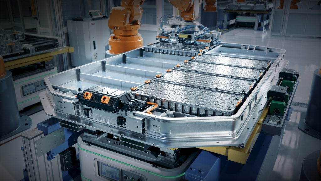
The electrochemical degradation mechanisms described above are well documented, but the cathode manufacturing process is a critical step that separates lithium precursor impurities from their ultimate effects in a finished cell. Understanding how impurities in lithium carbonate or lithium hydroxide actually matriculate, or fail to matriculate, through cathode synthesis and processing up into cell assembly is essential to evaluating which precursor specification limits are genuinely consequential and which are partially or fully redundant with downstream controls.
The Dilution Factor
The first and most basic consideration is stoichiometric dilution. In a typical layered oxide cathode, lithium constitutes roughly 7 to 10 percent of the final active material by mass, depending on the specific chemistry. However, it is important to base this dilution on the lithium compound actually charged to the blend (lithium carbonate or lithium hydroxide monohydrate) rather than on elemental lithium, because impurity limits are specified relative to the salt and the impurity travels with the full mass of that salt. Lithium accounts for only about 19 percent of lithium carbonate (and roughly 17 percent of lithium hydroxide monohydrate) by mass, so the lithium salt occupies a much larger share of the precursor blend than elemental lithium does. When a lithium precursor is blended with a co-precipitated transition-metal hydroxide precursor prior to calcination, the lithium salt typically constitutes on the order of 25 to 30 percent of the blend by mass, so impurities present in the lithium source are diluted by a factor of only about 3 to 4. A sodium level of 200 parts per million in lithium carbonate, for example, translates to a sodium contribution of roughly 50 to 60 parts per million in the blended precursor mix before any thermal or chemical processing has occurred.
This dilution means that the lithium precursor is one contamination vector among several, and not always the dominant one. The transition-metal hydroxide precursor, which constitutes most of the cathode mass, has its own impurity specification(s), its own supply chain(s), and its own contamination profile(s). In many cases, the absolute mass of a given impurity contributed by the transition metal precursor exceeds that contributed by the lithium source. A complete accounting of impurity risk in cathode manufacturing would require consideration of all material inputs into each component material, which is outside the scope of this white paper.
Sodium and Potassium
The most caution should be given to sodium and potassium impurities because the precursor specification is the sole control point for these elements, in contrast to the multi-stage defense available against the other impurity classes considered in this section. The Li/Na/K site substitution introduced in Section IV occurs during calcination at 700 to 900 °C, and the crystal structure is locked in on cooling. No washing step, surface treatment, or other post-calcination technique used in commercial cathode production can extract an alkali ion from an occupied lattice site. Whatever fraction of the precursor’s sodium and potassium load enters the lattice during calcination remains there for the life of the cell, and the precursor specification is the only control point that governs how much of the lithium-source contribution arrives at the calcination step in the first place.
Anions and Surface Residues
Anionic impurities (primarily sulfate, chloride, and residual carbonate) may or may not survive calcination depending on the specific anion, the calcination temperature, and the synthetic atmosphere, but even those that persist on the surface of calcined cathode particles are at least partially addressable through downstream processing.
Many high-nickel cathode producers perform an aqueous washing step after calcination to remove residual lithium compounds that form on cathode particle surfaces during cooling and atmospheric exposure. This washing step simultaneously removes water-soluble surface anion residues, including sulfate and chloride that survived calcination or were introduced during post-calcination handling. The effectiveness of washing at removing surface anions is well established, and it provides a second line of defense beyond the precursor specification.
That said, reliance on downstream washing is not without cost or risk. Aqueous washing exposes high-nickel cathode particles to moisture, which can leach lithium from the particle surface, alter the surface chemistry, and degrade electrochemical performance if not carefully controlled. Cathode producers invest significant process development effort in optimizing wash conditions such as water temperature, contact time, water-to-powder ratio, and drying protocol to balance surface cleaning against particle damage. Starting with a cleaner lithium precursor reduces the burden on the washing step, allowing less aggressive wash conditions and better preservation of cathode particle integrity. The precursor specification for anions is therefore not irrelevant, even though downstream processing provides partial redundancy. It is better understood as the first of two impurity control points rather than the sole control point.
Dissolved Ionic Transition Metals
Iron, copper, manganese, zinc, and other transition metal impurities present in dissolved ionic form in the lithium precursor behave differently from both the alkali metals and the anions. During calcination, these ions may substitute into the cathode crystal lattice (occupying transition metal sites or, less commonly, lithium sites), form secondary oxide phases dispersed within or between cathode particles, or reside at grain boundaries and particle surfaces as oxide inclusions.
In any of these configurations, the transition metal impurity is chemically bonded into the cathode material and is not removed by aqueous washing or magnetic separation. Washing removes water-soluble surface species; it does not extract iron or copper that has been incorporated into the layered oxide lattice during calcination. Magnetic separation, which is effective against metallic particles, does not capture ionic or oxidized transition metal impurities, which are paramagnetic or antiferromagnetic in bulk and exhibit at most weak, defect-mediated ferromagnetism at the nanoscale, which is well below the threshold required for capture by the drum or grate magnets used in standard CAM processing.
The precursor specification is therefore a primary control point for dissolved transition metal impurities, with an important caveat that the transition metal hydroxide precursor typically contributes the larger absolute mass of these impurities to the final cathode, and the lithium precursor’s contribution after the 3 to 4 times dilution is much smaller. Because the two contributions add up in the finished cathode, a low-transition-metal lithium source still matters since it lowers the total impurity load that the hydroxide precursor and downstream process controls must absorb.
Maintaining low transition-metal impurities is critical primarily to preserve the integrity of the cell over many cycles. Once the cell is built and cycling, a fraction of the transition metal population at or near the cathode particle surface migrates to the anode through a well-characterized chain known as the dissolution–migration–deposition (DMD) mechanism, or cathode-to-anode crossover. Surface and near-surface transition metals are released into the electrolyte by acid attack from solvent oxidation products, by disproportionation reactions, and by structural reconstruction at high states of charge; the dissolved cations migrate across the separator under the cell’s electric field and concentration gradient and are reduced onto the negative electrode, where they alter the composition and growth kinetics of the solid electrolyte interphase. In a conventional graphite-anode cell this deposition is largely absorbed within the SEI that forms on first cycle, and the impurity contribution typically manifests over hundreds of cycles as gradual capacity fade and rising impedance rather than as a single catastrophic failure mode. The relevant consequence for specification design is that the precursor-source contribution to the cathode’s dissolvable transition metal pool is not fully neutralized by dilution; it accumulates at the anode interphase over the life of the cell, and the rate at which it does so is one of the contributors to the long-cycle degradation that contemporary automotive cycle-life targets are increasingly pressing against. The same DMD chain becomes considerably more consequential when the negative electrode is metallic lithium, as discussed in Section VIII.
Metallic Particles
The metallic particle contamination pathway is distinct from the above because it is primarily a physical contamination problem rather than a chemical one. A metallic iron, stainless steel, or chromium particle originating from processing equipment at the lithium refinery enters the cathode manufacturing chain as a discrete physical object, not as a dissolved species. Its fate depends on its size, its composition, and the specific processing steps it encounters (i.e. the CAM processing flowsheet).
Calcination affects small and large metallic particles differently. Small particles tend to oxidize all the way through, converting to iron or chromium oxide and joining the dissolved ionic transition-metal population addressed above. Larger particles oxidize only at the surface, leaving a metallic core inside an oxide shell. These partially oxidized particles are the most critical to remove as they are the key facilitator of the killer-particle failure mode discussed in Section IV. The probability that any given particle reaches a finished cell intact is therefore set by two things: 1) the size distribution of the incoming particles; and 2) how completely they oxidize during processing. However, metallic particles face multiple removal opportunities throughout CAM manufacturing. Cathode producers run high-intensity magnetic separation after calcination and often again after electrode slurry mixing. Inline cleaning and inspection hardware integrated into coating and calendering lines (such as ionized-air or brush cleaners, or optical defect detection) provide additional catch points. However, calendering itself can also introduce fresh metallic abrasion from the rollers. Cell assembly includes additional inspection steps. Thus, the lithium precursor’s magnetic impurity specification is the first line of defense, but there are many opportunities to catch these impurities.
This multi-stage defense is important for understanding the complementary nature of the metallic impurity specification on the lithium precursor spec sheet and the cathode producer’s own magnetic separation capability. The precursor spec controls the incoming particle burden, while the cathode producer’s magnetic separation catches what gets through. The smaller the incoming burden, the lower the probability that a critical particle survives all downstream removal steps to reach the finished cell. Specification design for metallic impurities should therefore be understood in probabilistic terms as the goal is not zero particles (which is impractical) but a sufficiently low probability that any single particle survives the entire CAM manufacturing process.
Implications for Specification Design
This analysis of impurity fate through cathode manufacturing has direct implications for how precursor specifications should be evaluated and revised where warranted. Table 2 summarizes each lithium-precursor impurity class, their control points through CAM manufacturing, and provides a framework for assessing “Battery Grade” lithium precursor specifications based on those controls.
Table 2. Summary of lithium precursor impurities, their control points through the CAM manufacturing process, and their implication for “Battery Grade” lithium precursor specifications.
| Impurity class | Control points | Implication for Li precursor spec |
|---|---|---|
| Lattice-incorporating (Na, K, Fe, Cu, other transition metals) | Precursor specification only. There is no downstream removal once incorporated within the crystal structure of the CAM. | Set limits from the cathode chemistry’s electrochemical sensitivity. No relaxation predicated on the assumption of downstream processing removal. |
| Surface-residing anions (sulfate, chloride, residual carbonate) | Precursor specification and post-calcination washing (for sulfate and chloride). | Limits can reasonably credit a robust washing step. Modest relaxation may be justified where the cathode producer’s washing process is well-characterized. |
| Dissolved ionic transition metals (Fe, Cu, Cr, Ni) | Lithium-precursor spec and transition-metal hydroxide-precursor spec together. Calcination, washing, and magnetic separation do not remove the species once incorporated into the crystal structure of the CAM. | A tight lithium precursor limit matters most where it reduces the total transition-metal burden delivered to calcination. However, the transition-metal hydroxide precursor CAM (pCAM) carries most of this burden. |
| Metallic particles (Fe, Stainless Steel, Cu from milling media; tramp ferrous) | Precursor spec, post-calcination magnetic separation, post-slurry magnetic separation, inline cleaning/inspection on coating and calendering, cell-assembly inspection. | Set the incoming lithium specification to a level the downstream chain can probabilistically clear. |
This framework categorizes impurities by their fate through manufacturing and identifies where the precursor specification is the sole, primary, or supplementary control point. It provides a more rational foundation for specification design than the current approach, which treats all impurity limits as if they carry equal weight and offers no guidance on which ones matter most for a given cathode chemistry and manufacturing process.
VI. The Historical and Practical Basis
Not all specification thresholds can claim the kind of electrochemical pedigree described in Section IV. A significant fraction of the numbers on battery-grade lithium spec sheets were shaped by factors that are historical, analytical, or economic rather than strictly electrochemical.
Analytical Detection Limits as De Facto Specifications
When the first battery-grade lithium specifications were established in the late 1980s and early 1990s, the primary analytical tool for trace metal determination was inductively-coupled plasma optical emission spectrometry (ICP-OES). ICP-OES was and remains a capable technique, but its detection limits in lithium matrices at the time were in the single-digit ppm range for many elements of interest, and worse for elements suffering matrix interferences (notably Na and K, where the lithium-enriched plasma drives false positives). For some impurities, the practical detection limit of the available instrumentation was close to or indistinguishable from the specification threshold.
This constraint means that some early spec limits were effectively set at “below the detection limit of our instrument,” which was operationally equivalent to “as low as we can measure.” As analytical capabilities improved, particularly with the widespread adoption of ICP mass spectrometry (ICP-MS), which offers detection limits one to three orders of magnitude lower than ICP-OES for most elements, the ability to measure impurities outpaced the development of new electrochemical data to justify updating the thresholds. The specs that were set against 1990s-era ICP-OES detection limits often remained unchanged even as the industry gained the ability to detect and quantify impurities at far lower concentrations.
This analytical legacy cuts in both directions. For some impurities, the original detection-limit-based spec may have been adequate and the element in question may simply not be present in lithium precursors at levels that matter electrochemically, and the spec serves mainly as confirmation of absence. For others, particularly the transition-metals whose cumulative effects over thousands of cycles were not understood in the early 1990s, the detection-limit-based specification may have been insufficient. The point is that the specification was driven by what could be measured, not by what needed to be controlled. This distinction has become important as cycle life and reliability requirements have escalated over the decades.
Refining Route Constraints
The physical chemistry of lithium extraction and purification places its own constraints on achievable impurity levels. These constraints differ significantly depending on the initial lithium source. This divergence has left visible fingerprints on the specification framework.
Lithium carbonate derived from brine sources, historically the dominant production route, carries elevated levels of sodium, potassium, magnesium, and boron owing to the evaporative concentration process. The solar evaporation ponds that concentrate lithium from salar brines also concentrate these co-dissolved elements, and their removal during purification adds cost and process complexity. Sodium, in particular, is chemically similar to lithium and is among the most challenging impurities to separate. The specification limits for sodium in battery-grade lithium carbonate (see Table 1) represent a practical compromise between electrochemical preference and the economics of achieving tighter control from brine feedstocks. Beyond the salar’s native chemistry, the production wells themselves contribute impurities since hyper-saline brines aggressively corrode ferrous casings and downhole tubulars. This corrosion results in dissolving Fe (and Cr, Ni, and Mn from alloy steels) into the produced fluid, while drilling-tool wear leaves trace tungsten and cobalt from tungsten carbide/cobalt bits near the wellbore. These anthropogenic contributions vary pad-to-pad with infrastructure age and are not what the salar’s purification flowsheet was originally designed to remove.
Spodumene-derived lithium products carry different impurity signatures. Hard-rock mineral processing introduces iron, aluminum, and silicon from the ore body and from the grinding, roasting, and leaching equipment used in conversion. Iron contamination from stainless steel processing equipment is a persistent challenge in spodumene conversion plants and has driven significant investment in equipment metallurgy, ceramic linings, and process design to minimize metal pickup.
The influence of refining routes on specifications is most apparent in the treatment of boron. Boron is a meaningful impurity in brine-derived lithium products but is essentially absent in spodumene-derived material. Its presence on many battery-grade spec sheets reflects the dominance of brine production during the period when those specs were established. Electrochemically, boron is not a primary concern for most cathode chemistries at the levels typically found in purified lithium carbonate. Yet it persists as a specified parameter and a clear example of supply chain history imprinting itself on the specification framework.
Qualification Inertia
Perhaps the most powerful force preserving existing specifications is organizational. The qualification process that governs how cell manufacturers approve new materials creates a strong asymmetry where it is far easier to maintain an existing specification than to change one.
When a cell manufacturer qualifies a lithium precursor from a given supplier, the qualification is tied to a specific set of material properties, not just the specification limits but the actual delivered quality, including the typical values and statistical distributions observed during the qualification campaign. Any subsequent change to the specification, whether a tightening, a loosening, or even a change in the analytical method used to measure a parameter, technically constitutes a material change and can trigger requalification. The requalification process is expensive and time-consuming, typically requiring multiple cell builds, electrochemical testing over hundreds of cycles, safety testing, and review by the cell manufacturer’s quality and engineering teams. For automotive applications, the cell manufacturer’s requalification may itself need to be reviewed and approved by the automotive OEM, adding another layer of time and cost.
This structure creates a paradox. Specifications rarely loosen, even when accumulating electrochemical evidence suggests that certain thresholds are more conservative than necessary for a given cathode chemistry. Suppliers are reluctant to propose relaxation because it could be perceived as a quality concession, and cell manufacturers have little incentive to accept the requalification burden for a change that benefits the supplier’s economics more than the cell’s performance. Specifications also rarely tighten proactively, because tightening imposes new costs on the supplier and triggers the same requalification cycle. The result is that specifications tend to remain fixed at the level established during the initial qualification, even as the industry’s understanding of the underlying electrochemistry deepens and cell designs evolve.
The depth of this inertia is evident in the specification sheets themselves. One battery-grade lithium hydroxide specification reviewed for this work was traceable through multiple successive corporate entities over a period exceeding fifteen years, with the document number updated and the logo changed at each transition, but with zero numerical changes to any guaranteed limit on any parameter. The specification survived two acquisitions and a corporate restructuring entirely intact. This is not an isolated case; it reflects the structural reality that a qualified specification, once embedded in a cathode producer’s incoming quality system, becomes a quasi-permanent fixture that outlives the organizational identity of the company that first published it. The specification persists because no one has a sufficient incentive to bear the requalification cost of changing it.
One area where existing specifications have noticeably tightened over time is residual carbonate control for lithium hydroxide. Specifications from the early 2010s typically allowed 0.35% CO₂ as the maximum, a limit that appears across multiple producers and distributors from that era. More recent specifications from the mid-2010s forward increasingly specify 0.20–0.30% CO₂, with the tightest observed at 0.20%. This directional tightening follows the industry’s shift toward higher-nickel cathode chemistries (NMC 811, NCA) over the same period. These chemistries are far more sensitive to residual carbonate than their lower nickel counterparts. It stands as one of the clearer examples in the dataset of specification evolution driven by genuine technical need rather than by inertia or convention.
Standards Body Codification
The codification of battery-grade lithium specifications into national and international standards has followed industry practice. Early reagent-grade chemical-purity standards provided a reference point but were designed for general laboratory applications, not specifically for battery use. The more consequential standards development occurred in China, where the rapid growth of cathode material production drove the creation of standards specifically addressing battery-grade lithium precursors.
The Chinese standards GB/T 11075 (the national standard for industrial-grade lithium carbonate) and YS/T 582 (the nonferrous metals industry standard for battery-grade lithium carbonate) became de facto global references as Chinese refining capacity expanded to dominate global supply, with YS/T 582 in particular emerging as the dominant reference document for battery-grade material. These standards codified many of the impurity limits that had been established through bilateral negotiations between Chinese refiners and their cathode customer base, which by the 2010s included CATL, BYD, and the major Korean and Japanese cell manufacturers sourcing from Chinese material suppliers.
It is notable that no unified Western standard for battery-grade lithium carbonate or hydroxide has achieved comparable influence. ASTM International has published standards for lithium compounds, but these are oriented toward chemical characterization rather than battery-specific performance requirements. The absence of a coordinated Western standards effort has meant that Chinese standards, developed in tandem with the world’s largest lithium refining and cathode manufacturing complex, have effectively set the global baseline around which everyone else’s supply chains are organized. The consequence is that China also sets the technical definition of what “battery grade” means, which is a position of considerable leverage over both the transparency of global lithium supply chains and the pace at which their specifications can evolve.
VII. Carbonate vs. Hydroxide
The relationship between lithium carbonate and lithium hydroxide monohydrate has shifted fundamentally over the past decade, and this shift has had direct consequences for specification development. Understanding the divergence requires a brief detour into cathode synthesis chemistry.
High-Nickel Cathodes and the Evolution of LFP
Lithium carbonate was the original and, for two decades, the dominant lithium precursor for cathode synthesis. It remains the preferred input for lithium iron phosphate cathodes and for lower-nickel NMC formulations such as NMC 111 and NMC 523. For these chemistries, lithium carbonate’s lower cost, greater chemical stability, and simpler handling requirements make it the ideal choice.
However, the industry’s push toward higher energy density has driven the adoption of nickel-rich cathode formulations, such as NMC 622, NMC 811, NCA, and beyond, which increasingly require lithium hydroxide as the lithium source. The reason is that high-nickel cathode synthesis requires lower calcination temperatures, typically in the range of 700 to 800 °C, to suppress Li⁺/Ni²⁺ cation mixing. Because Li⁺ (0.76 Å) and Ni²⁺ (0.69 Å) have nearly identical ionic radii, Ni²⁺ readily occupies lithium sites in the layered NMC/NCA structure. At calcination temperatures above approximately 850 °C, two factors drive this mixing: (1) residual Ni²⁺ becomes increasingly difficult to fully oxidize to Ni³⁺ under achievable oxygen partial pressures, and (2) lattice oxygen loss generates oxygen vacancies that further promote Ni²⁺ migration into the lithium layer. The resulting cation disorder blocks lithium diffusion pathways and degrades both capacity and cycle life, with the effect intensifying as nickel content rises. This narrowed thermal window is what makes the choice of lithium source consequential. Lithium carbonate requires higher temperatures to fully react with the transition metal hydroxide or oxide precursors during solid-state synthesis. Lithium hydroxide, by contrast, can react at lower temperatures, enabling complete lithiation of high-nickel cathode materials within the thermal window that suppresses cation mixing.
Additionally, the use of lithium carbonate in nickel-rich cathode synthesis produces carbon dioxide as a byproduct of the carbonate decomposition. This evolved gas must be managed during calcination and can leave residual lithium carbonate on cathode particle surfaces if the reaction is incomplete (a condition that degrades electrochemical performance by creating an insulating surface layer). Lithium hydroxide avoids this issue, producing only water vapor as its byproduct.
The rapid adoption of LFP has driven a parallel evolution in battery-grade lithium carbonate specifications. LFP in general, and especially high-performance variants such as high-density LFP, has pushed cathode producers to scrutinize material properties they had previously overlooked. As compacted LFP electrode densities rose to close the volumetric energy gap with NMC, cathode producers added new physical-property requirements to their lithium carbonate specifications, including tighter controls on particle size and morphology to support the more uniform primary particles and higher compaction densities these formulations demand. However, the chemical-impurity limits that define battery-grade lithium carbonate, including the thresholds for sodium, potassium, sulfate, and the transition metals, remain anchored in the specifications inherited from the lithium cobalt oxide (LCO) and early NMC era and have not been systematically re-derived against the actual electrochemical sensitivities of modern LFP. The result is a specification framework that has adapted to LFP’s physical demands while leaving its chemical-impurity assumptions essentially untested against the chemistry it now serves.
How the Shift Changed Specification Priorities
The transition from carbonate to hydroxide as the preferred precursor for premium cathode chemistries introduced several new specification considerations for hydroxide that did not previously exist (or were not important) for carbonate.
Residual carbonate content became a critical specification for lithium hydroxide as it absorbs carbon dioxide from the atmosphere to form lithium carbonate. Therefore, the carbonate content of a lithium hydroxide shipment is a measure of its freshness and handling quality. Elevated carbonate levels indicate either prolonged atmospheric exposure or inadequate packaging. For high-nickel cathode synthesis, residual carbonate in the lithium hydroxide feedstock undermines the advantage of hydroxide. Typical specifications for residual carbonate in battery-grade lithium hydroxide range from 0.3 to 0.7 percent as lithium carbonate equivalent, with tighter limits demanded by the most advanced cathode producers.
Moisture control and packaging specifications also took on importance. Lithium hydroxide monohydrate is hygroscopic and will absorb additional water beyond its stoichiometric water of hydration if exposed to humid conditions. Excess moisture affects the material’s flowability and complicates dosing accuracy in cathode precursor blending. Specifications for free moisture content (water beyond the stoichiometric monohydrate) typically limit it to 0.1 to 0.3 percent, and packaging requirements often specify nitrogen-purged, moisture-barrier bags to maintain material integrity and compliance through the supply chain.
Physical property specifications (particle size distribution, bulk density, and flowability) emerged as specification categories that were largely absent from early lithium carbonate datasheets. Cathode synthesis processes are sensitive to the mixing homogeneity of the lithium source with the transition metal precursor, and particle size mismatch between the two inputs can lead to localized stoichiometric variations in the calcined cathode material. This drove the development of particle size specifications, typically expressed as D50 and span, that are tailored to match the particle characteristics of the co-precipitated transition metal hydroxide precursor being used by each NMC cathode manufacturer. A parallel evolution has taken place on the lithium carbonate side, driven by the LFP industry’s pursuit of higher compacted density. Modern high-density LFP cathodes are built from carefully engineered combinations of primary and secondary LiFePO₄ particles whose packing behavior is highly sensitive to the morphology and size distribution of the lithium carbonate input. LFP producers targeting compacted electrode densities above 2.5 g/cm³ have responded by specifying lithium carbonate with narrower D50 windows and controlled morphology parameters that did not appear on lithium carbonate datasheets a decade ago.
Is Hydroxide a Higher Value Product?
The price premium that lithium hydroxide commands over lithium carbonate has historically been attributed to its tighter specifications and more demanding production process, but it is worth examining whether the differential is fully justified by electrochemical necessity or partially reflects market structure. Hydroxide production from spodumene involves an additional processing step of causticization of lithium sulfate with sodium hydroxide or calcium hydroxide, followed by crystallization, which adds cost; production of lithium hydroxide from brine resources is even costlier still. Additionally, the tighter impurity specifications require more aggressive purification, further contributing to the differential. However, the relationship between specification tightness and price is not always linear as in some cases the premium may exceed the actual cost of meeting the tighter limits, with the difference representing a combination of qualification lock-in, limited supplier competition for qualified material, and the opacity of bilateral pricing between refiners and cathode producers.
VIII. Where Specifications May Need to Evolve
The specifications described in the preceding sections were developed for, and remain broadly adequate for, the generation of cell chemistries that dominated the 2000s and 2010s (lithium cobalt oxide consumer cells, lower-nickel NMC formulations, and traditional lithium iron phosphate cells for stationary and commercial vehicle applications). However, the industry is now deploying or developing chemistries and architectures that stress the existing framework in ways that its original designers did not anticipate.
High-Nickel Cathodes
Cathode formulations with nickel content at or above 60 percent of the transition metal composition (NMC 622, NMC 811, NCA, or emerging ultra-high-nickel variants approaching or exceeding 90 percent nickel) represent an immediate pressure point for existing specifications. These materials are structurally less stable than their lower-nickel predecessors, with a greater tendency toward cation mixing, surface reconstruction, and oxygen release during cycling. This reduced structural margin means that impurities that were tolerable in NMC 523 or NMC 622 can produce measurable degradation in NMC 811.
Sodium and potassium are areas of particular concern. At nickel contents above 80 percent, the layered structure is more susceptible to alkali metal substitution, and the rate capability and first-cycle efficiency penalties associated with Li/Na mixing become more pronounced. Some high-nickel cathode producers have already moved to sodium specifications below 100 ppm for their lithium hydroxide inputs, tighter than the 150 to 250 ppm range that was previously the standard.
Transition metal impurity requirements also face pressure as cycle life targets extend. Automotive applications are increasingly specifying cell lifetimes of > 1,000 cycles to meet vehicle warranty requirements and support second-life applications. Over these extended cycle counts, the cumulative effect of iron and copper dissolution and redeposition becomes more significant, and impurity levels that produced no detectable effect in 300-cycle qualification testing may emerge as degradation contributors over the full life of the cell. This misalignment creates a fundamental rift between the qualification testing horizon and the performance requirements of the end application.
High-Density LFP
If high-nickel cathodes are the pressure point on the hydroxide side, high-density and other exotic variants of LFP are the corresponding pressure point on the carbonate side, and one that has received considerably less attention in specification discussions despite LFP’s commanding share of global cell production. Successive generations of LFP, sometimes described in the industry as third- and fourth-generation LFP, and increasingly as LMFP where manganese is added to the olivine structure, have steadily raised compacted electrode density and gravimetric capacity, narrowing the volumetric energy gap with low- and mid-nickel NMC that was once treated as LFP’s defining limitation.
These gains rest on tighter control of the cathode active material’s particle architecture, which in turn rests on tighter control of the lithium carbonate feedstock. Achieving the high tap and compacted electrode densities that distinguish modern LFP from earlier generations requires a bimodal or carefully graded mixture of primary and secondary particles, and the morphology of those particles is influenced at the synthesis stage by the size, shape, and reactivity of the lithium carbonate input. As a result, LFP cathode producers have begun specifying physical parameters for lithium carbonate precursor material, such as D50, bulk density, and tap density, at a level of granularity that earlier LFP generations did not require.
Impurity classes that were treated as second-order for older LFP have also become first-order for high-density LFP. Sulfate residuals, which at moderate levels were tolerable in lower-density LFP, can interfere with the controlled crystallization needed for engineered particle morphologies and contribute to gas generation during cell formation. Magnetic and ferrous impurities, long flagged for safety reasons, are increasingly being specified at single-digit ppb levels by leading LFP producers, because the same low cell impedance that enables fast charging also amplifies the consequences of any internal short-circuit nucleus.
The specification framework for lithium carbonate, in other words, is being rewritten in service of high-density LFP much as the framework for lithium hydroxide was rewritten in service of high-nickel NMC, but the rewrite has been less visible because it has unfolded gradually inside bilateral supplier-producer relationships rather than as a marketed step change in product grade.
Lithium Metal Anodes
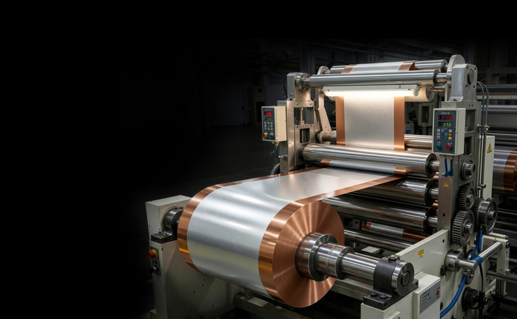
The development of lithium metal anodes, whether as thin lithium foil in conventional liquid electrolyte cells or in solid-state architectures, may expose lithium-ion cells to failure modes that are second-order in graphite-anode systems but become first-order when the negative electrode is metallic lithium. The relevant question for precursor specifications is therefore not only what enters the lithium source but what survives the lines of defense in CAM manufacturing described in Section V and arrives at the finished cathode, where it can act on a lithium metal anode in ways that decades of qualification on graphite-anode cells have not characterized.
Two of the impurity classes catalogued in Section V carry the most asymmetric risk in a lithium metal anode cell. The first is dissolved transition metals (iron, copper, chromium, etc.) that incorporate into the cathode lattice during calcination and are not removed by any downstream processing. The dissolution–migration–deposition chain by which a fraction of these species migrates to the anode during cycling is described in Section V; what changes when the negative electrode is metallic lithium is the downstream consequence rather than the mechanism. In a graphite-anode cell, any initial crossover deposition is largely absorbed within the solid electrolyte interphase that forms on first cycle, and the impurity contribution shows up over hundreds of cycles as gradual capacity fade and rising impedance. In a lithium metal anode cell, the same crossover species reduce directly onto the plating surface, where they act as heterogeneous nucleation sites for subsequent lithium deposition and bias morphology toward dendritic rather than smooth, dense plating. The second is metallic particles that survive the magnetic-separation and inspection gauntlet described in Section V. The killer-particle failure mode discussed in Section IV is already the principal safety concern for these particles in a conventional cell; in a lithium metal anode cell the same surviving particle population also has direct access to the plating surface, where even particles that are too small to puncture a separator can seed dendrite growth that ultimately does.
The implication for precursor specifications is that the impurity limits that have been treated as adequately controlled by downstream CAM processing in graphite-anode cells may not be adequate for cells paired with a lithium metal anode. In particular, the transition-metal-impurity limit on the lithium precursor has historically been justified in part by the dilution effect introduced in Section V and by the assumption that any residual lattice incorporation is absorbed without consequence in the SEI of a graphite anode. Neither assumption holds when the negative electrode is metallic lithium. The qualification work to translate this difference into revised specifications has not yet been done, and lithium metal anode cells are currently a small enough share of commercial production that the existing precursor specifications have not been stress-tested against their requirements.
A similar argument applies to silicon and silicon-composite anodes, with the additional consideration that they are considerably closer to mass-market deployment than lithium metal. The silicon anode operates closer to lithium plating potential than graphite, undergoes substantial volume expansion on lithiation that repeatedly breaks and reforms the solid electrolyte interphase, and exposes the impurities it accumulates more directly to the electrochemically active surface than a stable graphite SEI does. The result is that the same crossover and metallic-particle vulnerabilities described above for lithium metal apply in attenuated form to silicon, with the impurity dose seen by the anode interphase rising over cycle life rather than appearing all at once. Unlike lithium metal, silicon-composite anodes are already in or near series production. Several silicon-anode material suppliers (including Sila Nanotechnologies, Group14 Technologies, Amprius Technologies, and OneD Battery Sciences) are in active commercial programs with automotive, consumer-electronics, and aerospace customers, and at least one major automaker has integrated silicon nanotechnology into its next-generation cell development. As these chemistries move from pilot to volume manufacturing, they will provide the first commercial-scale test of whether precursor specifications calibrated to graphite-anode cells remain adequate for negative electrodes that share lithium metal’s heightened sensitivity without yet sharing its production-volume problem.
Solid-State Electrolytes
Solid-state electrolytes, whether sulfide-based, oxide-based, or halide-based, introduce new classes of impurity sensitivity that are not captured by current lithium precursor specifications. Sulfide electrolytes, for example, are extremely moisture-sensitive; even parts-per-million levels of water can cause hydrolysis of the sulfide phase, releasing hydrogen sulfide gas and degrading ionic conductivity. If lithium precursors used in sulfide electrolyte synthesis carry residual moisture or adsorbed water beyond what current specifications control, they can serve as a contamination source that undermines the electrolyte’s performance.
Halide electrolytes introduce concerns about cross-contamination between different halide species (for example, chloride contamination of a bromide-based electrolyte) that are entirely absent from current specification frameworks. Oxide electrolytes such as garnet-type lithium lanthanum zirconium oxide require lithium precursors with controlled particle size and reactivity to achieve the high sintering densities needed for adequate ionic conductivity, adding physical property specifications that go beyond what is standard for cathode precursor applications.
These emerging electrolyte technologies are at varying stages of commercialization, and their specification requirements remain in active development. However, they illustrate a broader point that the assumption of a single set of “battery-grade” lithium precursor specifications can serve all battery applications is becoming increasingly untenable as the diversity of cell architectures expands.
Emerging Cathode Chemistries
Beyond the incremental evolution of high-nickel layered oxides and improved LFP, additional chemistries are moving from research into early commercial development and could place a different set of demands on lithium precursor specifications. Lithium- and manganese-rich layered oxides demonstrate this point most clearly (the chemistry behind several next-generation automotive cell programs, including General Motors’ announced LMR cathodes for Ultium platform extensions) and disordered rocksalt (DRX) oxyfluorides (the subject of scalable-synthesis development at Lawrence Berkeley National Laboratory and at battery-materials companies such as Wildcat Discovery Technologies). Both abandon cobalt, lean heavily on earth-abundant manganese, and target cathode-level energy densities at or above 900 Wh/kg, a substantial step beyond what high-nickel NMC delivers today.[44] What they share with high-nickel cathodes is structural fragility under cycling; what they introduce that is genuinely new is sensitivity to specific impurity classes that the inherited specification framework was not built to control.
Lithium- and manganese-rich cathodes suffer from a well-documented voltage-decay problem driven by oxygen release and transition metal rearrangement at the cathode surface during high-voltage cycling, and the resulting Mn dissolution is the most aggressive variant of the dissolution–migration–deposition chain introduced in Section V. Mn²⁺ is the canonical species for SEI poisoning on graphite anodes; in a chemistry where manganese is the majority transition metal rather than a minor constituent, even modest increases in the dissolvable transition metal pool from precursor-source contamination translate into a proportionally larger anode-side impurity during cycling. Equally important, sodium and potassium, which migrate into the layered structure during calcination, are known to suppress oxygen redox instability when introduced as deliberate dopants; their uncontrolled presence as precursor impurities can therefore have either beneficial or detrimental effects depending on level and distribution, which is not a behavior the current alkali-metal specifications were derived to manage.
DRX cathodes present an additional set of considerations. Their stable cycling depends on substantial fluorine substitution for oxygen in the rocksalt lattice, and the synthesis chemistry is correspondingly sensitive to species that compete with fluorine for incorporation or that disrupt the low-temperature solid-state reaction pathways currently being developed to retain fluorine in the bulk of the material. Residual moisture and carbonate in the lithium source, both of which are controlled in the current framework primarily for their effects on high-nickel cathode synthesis, take on a different significance when the calcination chemistry is built around an oxyfluoride lattice rather than a layered oxide. The high lithium-to-transition-metal ratios characteristic of DRX (lithium-excess compositions with Li/M well above unity) also mean the per-cathode mass contribution from the lithium precursor is larger than in NMC or LFP, eroding part of the dilution buffer that Section V described and making low-level lithium-source impurities proportionally more consequential in the finished cathode.
Neither chemistry has been produced at the scale needed for the kind of qualification feedback loop that shaped the existing specifications for layered oxide and olivine cathodes. As they move toward commercialization, they will require precursor specifications that are not simply tightened versions of the current battery-grade limits but that target a different set of impurity classes. Specifically, the species that most strongly modulate manganese dissolution kinetics, oxygen redox stability, and (for DRX) fluorine retention during synthesis will need to be carefully evaluated.
New CAM Manufacturing Routes
A more fundamental shift may come from new ways of making the dominant existing cathode materials. The carbonate–hydroxide dichotomy that underpins today’s specification landscape reflects the synthesis routes that have dominated cathode production to date, in which lithium carbonate or lithium hydroxide is the compound delivered to the cathode producer. As new and alternative cathode synthesis routes emerge, the lithium precursor delivered into the process may no longer be limited to these two compounds. Other lithium salts, such as lithium sulfate, lithium chloride, or lithium dihydrogen phosphate, could become direct precursors to cathode active material under certain process configurations, bypassing the conversion to carbonate or hydroxide that is standard today.
Should that occur, the industry will face the same question this paper has posed for carbonate and hydroxide, which is what does a defensible “battery-grade” specification look like for that compound? There would be no inherited body of qualification data to draw on, and the temptation would be to set limits by analogy to the existing carbonate and hydroxide specifications rather than from first principles. The framework advanced in this paper of deriving impurity limits from the cathode chemistry’s electrochemical sensitivity and the demonstrated control points through manufacturing also applies equally to any lithium precursor, regardless of its chemical form, and would provide a more rational starting point for these salts than carrying over limits that were never designed for them.
Non-Electrochemical Dimensions
Further dimensions are beginning to appear on specification sheets that do not have an electrochemical basis but may prove equally consequential from a procurement perspective. One dimension is the environmental footprint of the material. At least one major lithium producer now includes lifecycle carbon emissions data directly on its battery-grade product data sheet, reporting CO₂ equivalent intensity per kilogram of product alongside the traditional chemical purity and impurity parameters. The inclusion of this specification signals that carbon intensity is entering the conversation as a de facto procurement criterion, driven by European Battery Regulation requirements and automotive OEM sustainability commitments. While carbon footprint is not a chemical specification in the traditional sense, its appearance on product data sheets alongside impurity limits suggests that the next generation of “battery-grade” specifications may need to accommodate dimensions that the original framers of the specification framework never contemplated.
IX. Toward Rational Specification Design
If the existing specification framework is a product of history as much as electrochemistry, the question of what a more rational approach would look like merits consideration. Several principles suggest themselves.
Electrochemically Derived Specifications
The most fundamental shift would be to derive impurity thresholds from cell-level degradation studies rather than from historical precedent or supply capability. This means conducting systematic experiments in which individual impurities are intentionally introduced into cathode precursors at controlled concentrations, and the resulting cells are tested over cycle counts and under conditions that reflect actual application requirements. Some such studies exist in academic literature for some impurities and some cathode chemistries, but they are far from comprehensive, and their results are not always translated into specification guidance that is accessible to the broader supply chain.
An electrochemistry-first approach would also account for the interaction effects between impurities. The current specification framework treats each impurity independently, but there is evidence that certain combinations of impurities, such as iron and sulfate together, can produce degradation effects that are more than additive.Capturing these interactions would require designed experiments that go beyond the one-element-at-a-time approach that has dominated the literature.
Chemistry-Specific Specifications
A second principle is that specifications should be tailored to the cathode chemistry and cell application, rather than applied as a one-size-fits-all framework. The impurity sensitivity of lithium iron phosphate is fundamentally different from that of NMC 811, which is different again from the requirements of a lithium metal anode cell. A tiered specification system with different impurity limits for battery chemistries could better align supply chain costs with actual performance requirements.
This type of system could reduce costs for applications where existing specifications are unnecessarily tight. Lithium iron phosphate cathodes, for example, are known to be relatively tolerant of sodium and potassium impurities at levels well above what current battery-grade specifications allow. Relaxing alkali metal limits for LFP-grade lithium carbonate could expand the pool of qualifying material and reduce the refining cost premium without any electrochemical penalty. Conversely, high-nickel cathode applications may require tighter control of transition metal impurities than current specifications provide, and a chemistry-specific framework would make those tighter requirements explicit rather than leaving them to bilateral negotiation between individual cathode producers and their lithium suppliers.
Advanced Analytical Methods
The analytical tools available for impurity characterization have advanced dramatically since the specifications were first established. Single-particle ICP-MS can characterize impurities at the level of individual cathode particles, revealing heterogeneities that bulk analysis averages away.Total-reflection X-ray fluorescence offers non-destructive trace element analysis with detection limits in the sub-ppb range. Laser ablation ICP-MS enables spatially resolved impurity mapping within cathode coatings and individual particles. These techniques can provide the kind of data needed to understand which impurities, at which concentrations, and in which spatial distributions, actually drive cell-level degradation, which is the information that can allow us to move away from historically inherited specifications to electrochemically rational ones.
Industry Collaboration and Pre-Competitive Data Sharing
Rational specification design requires data that no single company is likely to generate on its own. Systematic impurity sensitivity studies across multiple cathode chemistries, conducted with statistical rigor over cycle counts relevant to real applications, represent a significant investment. Pre-competitive industry collaboration could accelerate progress in this area. Organizations such as NAATBatt International, the Batteries European Partnership Association (BEPA), and various national laboratory consortia are positioned to coordinate this kind of work, and some efforts in this direction are already underway.
The key deliverable from such collaboration would be publicly available, chemistry-specific impurity sensitivity data that would allow suppliers, cathode producers, cell manufacturers, and OEMs to negotiate specifications based on shared evidence rather than inherited convention. This transparency would not replace the competitive differentiation that cell manufacturers achieve through their proprietary processing and cell design expertise, but it would provide a common empirical foundation for the material specifications that underpin the entire supply chain.
X. Conclusion

The specifications that define battery-grade lithium carbonate and lithium hydroxide are not wrong. They were fit for purpose in the era that produced them, and they have served the industry through a period of extraordinary growth from Sony’s first commercial lithium-ion cell in 1991 to a global industry producing hundreds of gigawatt-hours of cells per year.[4] The engineers and chemists who established these specifications were working with the analytical tools, the electrochemical understanding, and the supply chain realities available to them, and many of the thresholds they set were more right than they could have fully known at the time.
However, the industry has changed in ways that strain the original framework. Cathode chemistries have evolved from lithium cobalt oxide to nickel-rich formulations that are more sensitive to certain impurities. Cycle life requirements have extended from hundreds of cycles to thousands. Entirely new cell architectures (lithium metal anodes, solid-state electrolytes) are emerging with impurity sensitivity profiles that the existing spec sheets were never designed to address. And the supply base has transformed from a handful of South American brine producers to a globally distributed network of brine, spodumene, and direct lithium extraction operations, each with their own characteristic impurity fingerprint.
The opportunity that this creates is significant. A move toward rational, electrochemistry-driven, chemistry-specific specifications could deliver simultaneous benefits in reducing cost by relaxing thresholds that impose unnecessary refining burden for a given application, and improving performance by tightening the thresholds that actually matter for the most demanding next-generation chemistries. Achieving this will require investment in systematic impurity sensitivity research, willingness to revisit qualification frameworks that have resisted change for decades, and a degree of pre-competitive data sharing that the industry has historically been reluctant to undertake.
This challenge is compounded by the emergence of new lithium extraction technologies. Direct lithium extraction produces material with an impurity fingerprint distinct from both conventional brine evaporation and spodumene conversion. DLE-derived lithium carbonate may carry different ratios of sodium, chloride, and sulfate depending on the sorbent, solvent, or membrane chemistry employed, and these profiles do not map neatly onto a specification framework designed around 1990s-era brine and hard-rock operations. As DLE scales to commercial production, the case for source-aware, chemistry-specific specifications becomes even more pressing.
The starting point is simply understanding where the current specifications came from. This understanding is not offered as a criticism of the people and institutions that established them, but as a necessary foundation for deciding, with evidence rather than inertia, what they should become.
Acknowledgements
The authors would like to acknowledge Samuel Dahlhauser and Amit Patwardhan for their feedback on previous drafts of this white paper and their suggestions on topics to include.
About EnergyX
EnergyX (Energy Exploration Technologies, Inc.) is a Lithium Extraction Company developing direct lithium extraction technology and refining processes to deliver battery-grade lithium products, including lithium carbonate, lithium hydroxide, and lithium dihydrogen phosphate, for the global energy transition.
References
- Whittingham, M.S. (1976). “Electrical Energy Storage and Intercalation Chemistry.” Science 192(4244), 1126–1127.
- Mizushima, K.; Jones, P.C.; Wiseman, P.J.; Goodenough, J.B. (1980). “LiₓCoO₂ (0<x≤1): A New Cathode Material for Batteries of High Energy Density.” Materials Research Bulletin 15(6), 783–789.
- Yoshino, A. (2012). “The Birth of the Lithium-Ion Battery.” Angewandte Chemie 51(24), 5798–5800.
- Nagaura & Tozawa (1990), “Lithium Ion Rechargeable Battery,” Progress in Batteries & Solar Cells 9, 209.
- Garrett, D.E. (2004), Handbook of Lithium and Natural Calcium Chloride.
- Ebensperger et al. (2005), “The lithium industry: Its recent evolution and future prospects.” Resources Policy 30(3), 218–231.
- Murphy, O., & Haji, M. N. (2022). “A review of technologies for direct lithium extraction from low Li+ concentration aqueous solutions.” Frontiers in Chemical Engineering 4, 1008680.
- NIST SRM 924a, Lithium Carbonate (Standard Reference Material, certified mass fraction 99.867%). National Institute of Standards and Technology.
- Composite source: representative supplier certificates of analysis (e.g., Albemarle, SQM, Ganfeng battery-grade datasheets), together with GB/T 11075–2013 (Lithium Carbonate) and YS/T 582–2013 (Battery-Grade Lithium Carbonate) standards.
- Arora, P. et al. (1998), “Capacity fade mechanisms and side reactions in lithium-ion batteries.” J. Electrochem. Soc.
- Fear, C., Juarez-Robles, D., Jeevarajan, J. A., & Mukherjee, P. P. (2018). “Elucidating copper dissolution phenomenon in Li-ion cells under overdischarge extremes.” Journal of The Electrochemical Society 165(9), A1639–A1647.
- Buchberger et al. (2015), “Aging analysis of graphite/LiNi₁/₃Mn₁/₃Co₁/₃O₂ cells.” J. Electrochem. Soc. 162(14), A2737.
- Bhandari, A., & Bhattacharya, J. (2017). “Manganese dissolution from spinel cathode: few unanswered questions.” Journal of The Electrochemical Society 164(2), A106–A127.
- Shin, H., et al. (2015). “Degradation of the solid electrolyte interphase induced by the deposition of manganese ions.” Journal of Power Sources 284, 416–427.
- A) Gilbert, J. A., Shkrob, I. A., & Abraham, D. P. (2017). “Transition metal dissolution, ion migration, electrocatalytic reduction and capacity loss in lithium-ion full cells.” Journal of The Electrochemical Society 164(2), A389–A399. B) Zhan, C., Wu, T., Lu, J., & Amine, K. (2018). “Dissolution, migration, and deposition of transition metal ions in Li-ion batteries exemplified by Mn-based cathodes: a critical review.” Energy & Environmental Science 11(2), 243–257.
- A) Lu, Z., Donaberger, R. A., & Dahn, J. R. (2000). “Superlattice ordering of Mn, Ni, and Co in layered alkali transition metal oxides with P2, P3, and O3 structures.” Chemistry of Materials 12(12), 3583–3590. B) Ates, M. N., et al. (2014). “Mitigation of layered to spinel conversion of a Li-rich layered metal oxide cathode material for Li-ion batteries.” Journal of The Electrochemical Society 161(3), A290–A301.
- Shannon, R.D. (1976), “Revised Effective Ionic Radii.” Acta Crystallographica A32, 751–767.
- Noh et al. (2013), “Thermal stability and calcination temperature requirements for high-Ni cathodes.” J. Power Sources 233, 121–130.
- Sattar, T., et al. (2020). “Effect of Mg-doping on the electrochemical performance of LiNi₀.₈₄Co₀.₁₁Mn₀.₀₅O₂ cathode for lithium ion batteries.” International Journal of Hydrogen Energy 45(38), 19567–19576.
- Tsuda, T., Stafford, G. R., & Hussey, C. L. (2017). “Electrochemical surface finishing and energy storage technology with room-temperature haloaluminate ionic liquids and mixtures.” Journal of The Electrochemical Society 164(8), H5007–H5017.
- Schmidt, F., et al. (2022). “Influence of external stack pressure on the performance of Li-S pouch cell.” Journal of Physics: Energy 4(1), 014004.
- Feng, Y., et al. (2026). “Precisely modulating Li₂CO₃ coverage on Ni-rich cathode boosts sulfide solid-state lithium battery performance.” Chem 12(3).
- Mohanty et al. (2016), “Effect of electrode manufacturing defects on electrochemical performance.” J. Power Sources 312, 70–79.
- S.G. Frantz Co., “Magnetic Separators and Lithium-Ion Batteries” (supplier technical documentation), https://sgfrantz.com/magnetic-separators-and-lithium-ion-batteries/.
- Nitta, N.; Wu, F.; Lee, J.T.; Yushin, G. (2015). “Li-ion battery materials: present and future.” Materials Today 18(5), 252–264.
- Zheng, J.; Yan, P.; Estevez, L.; Wang, C.; Zhang, J.G. (2018). “Effect of calcination temperature on the electrochemical properties of nickel-rich LiNi₀.₇₆Mn₀.₁₄Co₀.₁₀O₂ cathodes.” Nano Energy 49, 538–548.
- Manthiram, A.; Song, B.; Li, W. (2017). “A perspective on nickel-rich layered oxide cathodes for lithium-ion batteries.” Energy Storage Materials 6, 125–139.
- Seong, W. M., Kim, Y., & Manthiram, A. (2020). “Impact of residual lithium on the adoption of high-nickel layered oxide cathodes for lithium-ion batteries.” Chemistry of Materials 32(22), 9479–9489.
- Jo, C.H.; Cho, D.H.; Noh, H.J.; Yashiro, H.; Sun, Y.K.; Myung, S.T. (2015). “An effective method to reduce residual lithium compounds on Ni-rich Li[Ni₀.₆Co₀.₂Mn₀.₂]O₂.” Nano Research 8, 1464–1479.
- Zheng, J., Ye, Y., & Pan, F. (2020). “‘Structure units’ as material genes in cathode materials for lithium-ion batteries.” National Science Review 7(2), 242–245.
- Kwade, A.; Haselrieder, W.; Leithoff, R.; et al. (2018). “Current status and challenges for automotive battery production technologies.” Nature Energy 3, 290–300.
- Boss & Fredeen (1997), Concepts, Instrumentation and Techniques in ICP-OES.
- Thomas (2013), Practical Guide to ICP-MS.
- Munk et al. (2016), “Lithium brines: A global perspective.” Reviews in Economic Geology 18, 339–365.
- Kavanagh, L., et al. (2018). “Global lithium sources: industrial use and future in the electric vehicle industry: a review.” Resources 7(3), 57.
- GB/T 11075–2013 (Lithium Carbonate) and YS/T 582–2013 (Battery-Grade Lithium Carbonate) standard documents.
- An, R., et al. “Storage Failure Mechanisms and Modifications of Ni-Rich Cathode Materials: From Polycrystalline to Single-Crystal Forms.” Chinese Journal of Chemistry 43.7 (2025): 823-840.
- Duan, Y., et al. “Insights into Li/Ni ordering and surface reconstruction during synthesis of Ni-rich layered oxides.” Journal of Materials Chemistry A 7.2 (2019): 513-519.
- Tran, N. T. T., Lin, C.-A., & Lin, S.-K. (2023). “Insights into the structural and thermodynamic instability of Ni-rich NMC cathode.” ACS Sustainable Chemistry & Engineering 11(18), 6978–6987.
- A) U.S. DRIVE, Electrochemical Energy Storage Technical Team Roadmap (U.S. DRIVE Partnership / U.S. Advanced Battery Consortium, latest edition), establishing EV cell- and pack-level cycle-life and calendar-life targets (≈1,000 cycles, 15-year calendar life). B) Duffner, F., et al. (2021). “Opportunities and Challenges of Lithium Ion Batteries in Automotive Applications.” ACS Energy Letters 6(2), 386–396. Typical OEM EV warranties (8-year / ~1,000-cycle) reflect these targets in commercial practice.
- Wood, S. M., et al. (2016). “K⁺ reduces lithium dendrite growth by forming a thin, less-resistive solid electrolyte interphase.” ACS Energy Letters 1(2), 414–419.
- Muramatsu, H., et al. (2011). “Structural change of Li₂S–P₂S₅ sulfide solid electrolytes in the atmosphere.” Solid State Ionics 182(1), 116–119.
- Murugan, R., Thangadurai, V., & Weppner, W. (2007). “Fast lithium ion conduction in garnet-type Li₇La₃Zr₂O₁₂.” Angewandte Chemie International Edition 46(41), 7778–7781.
- Nasser, O. A., & Petranikova, M. (2021). “Review of achieved purities after Li-ion batteries hydrometallurgical treatment and impurities effects on the cathode performance.” Batteries 7(3), 60.
- Luo, X., Li, Y., & Cheng, X. (2023). “Mechanistic study in sulfur-carbon co-modification on Li2FeSiO4 for lithium-ion batteries.” Ceramics International 49(16), 27277–27287.
- Cui, H., et al. (2026). “Revitalising spent LiFePO4 electrodes via a dual-factor response mechanism for enhanced lithium extraction from brines.” Desalination, 120296.
- Montoro Bustos, A. R. (2024). “ICP-MS-Based Characterization and Quantification of Nano- and Microstructures.” Nanomaterials 14(7), 578.
- Harte, P., et al. (2019). “Adaptation and improvement of an elemental mapping method for lithium ion battery electrodes and separators by means of laser ablation-inductively coupled plasma-mass spectrometry.” Analytical and Bioanalytical Chemistry 411(3), 581–589.